Making My Beautiful Hair
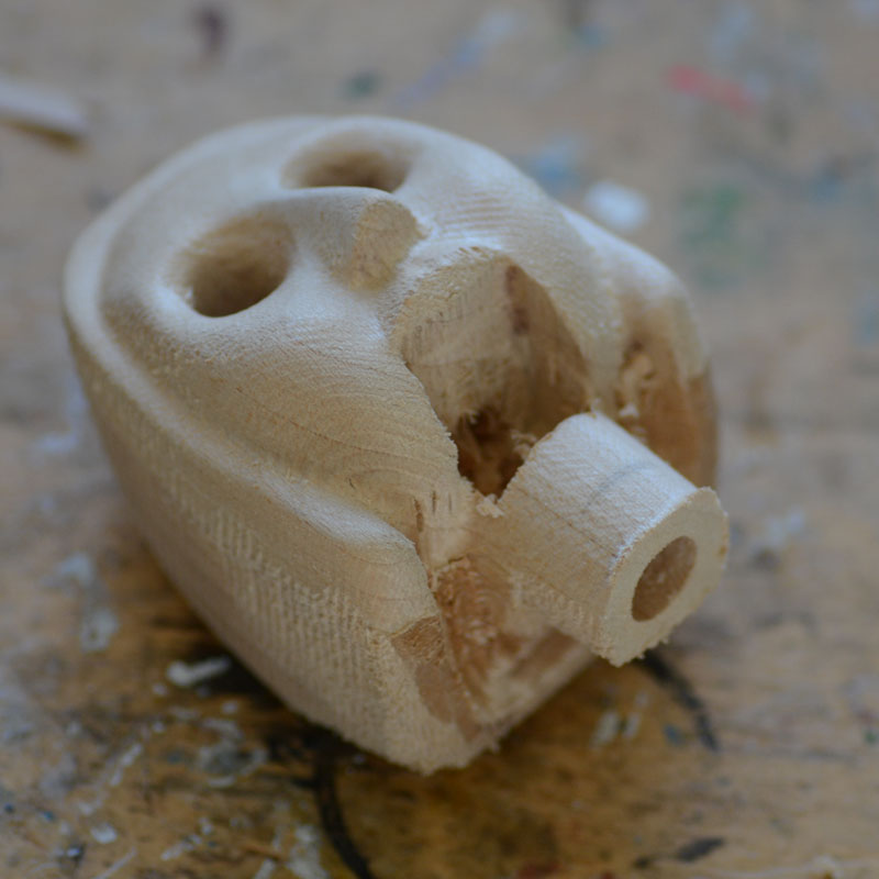
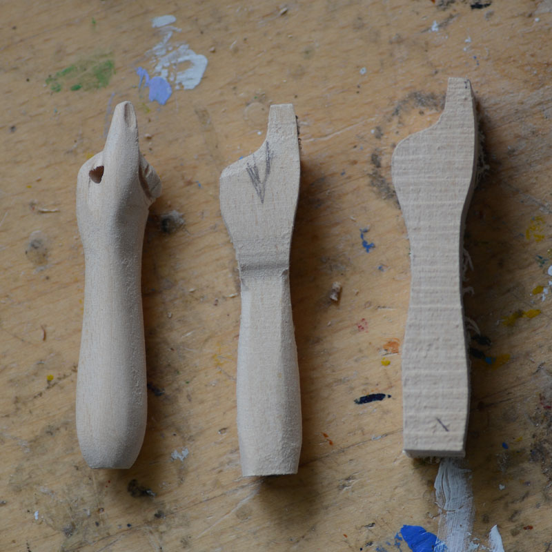
Head blank in lime wood
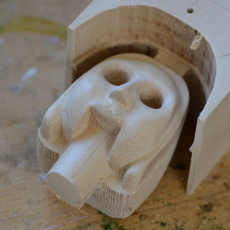
Head blank being prepared
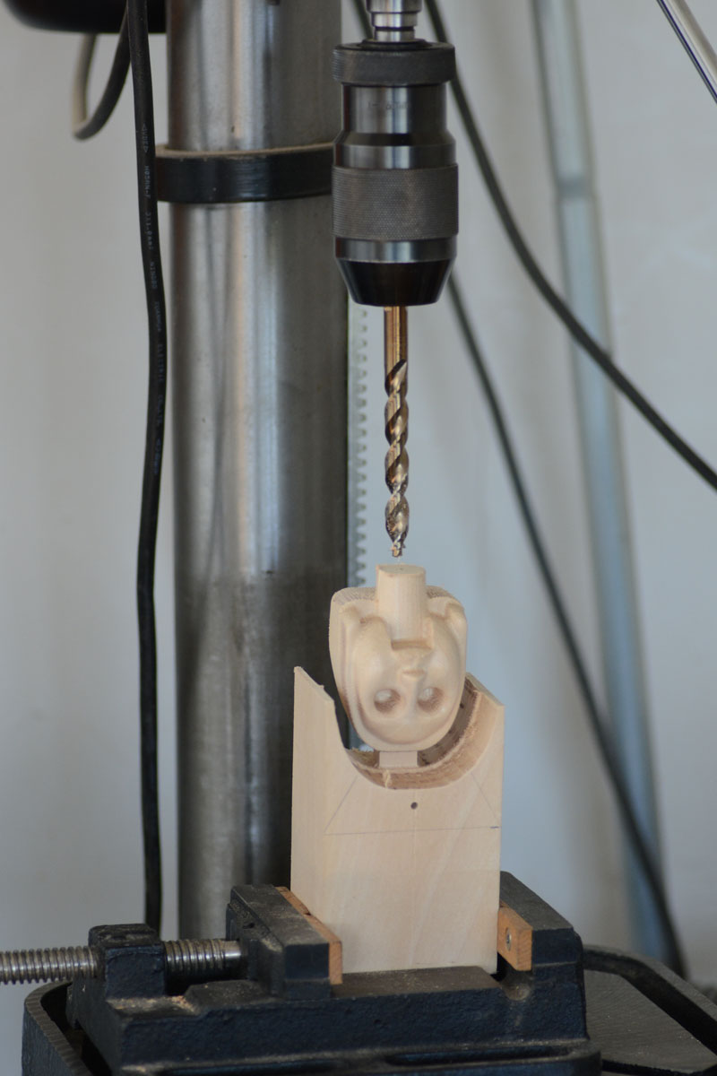
Drilling neck
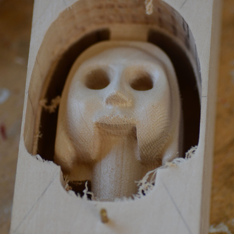
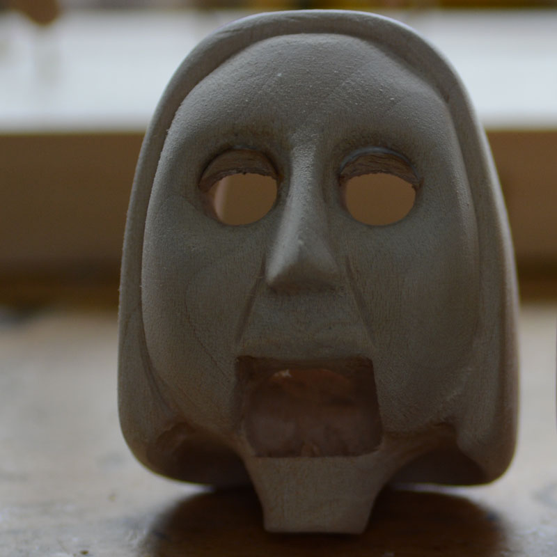
Head blank ready for hand carving and finishing.It takes several hours to get from this stage to a finished head ready for painting.
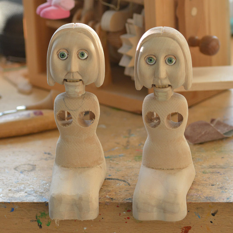
Head with eyelids fitted. The eyelids are cut from beechwood which is harder and tougher than the lime that the head is carved from.
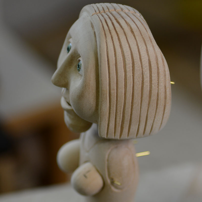
Head with hair carved. The eyes have been trial fitted as have the breasts and the lower jaw.. The shape of the dress has been carved.
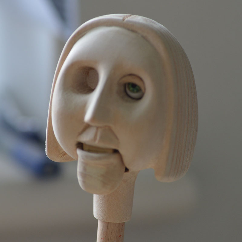
Showing placement of eyelash with eye positioned to check position. The eyelids will be ground internally to fit the eyes.
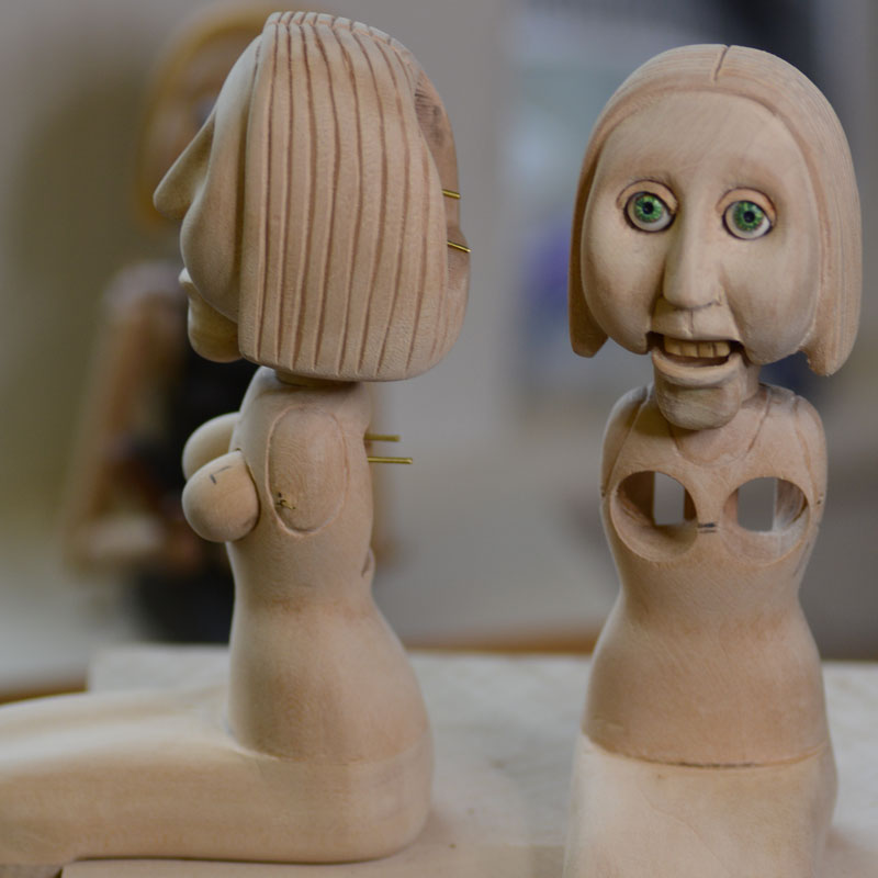
Showing placement of teeth. The teeth are carved from box wood. This is very finely grained and gives a very smooth finish.
Arms and hands hand cut and carved,
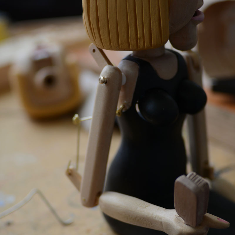
Dress carved and glued onto the upper body. This assembly has been drilled through to take the head controls and also the "breathing" controls. The original prototype made in 2009 can be seen in the background.
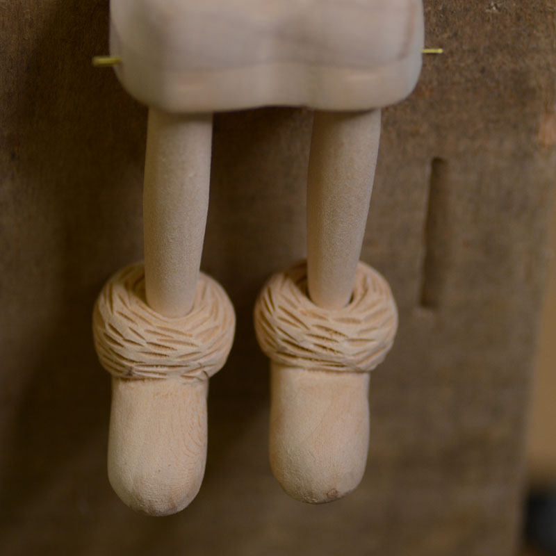
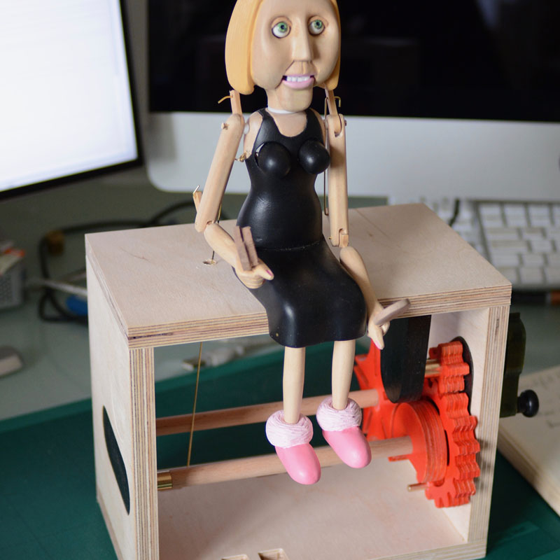
Slippers carved from lime wood.
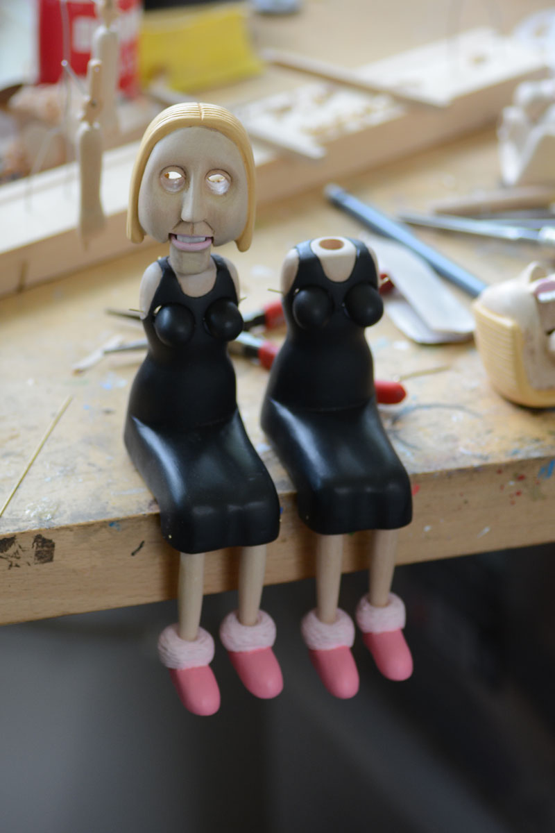
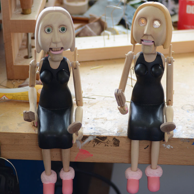
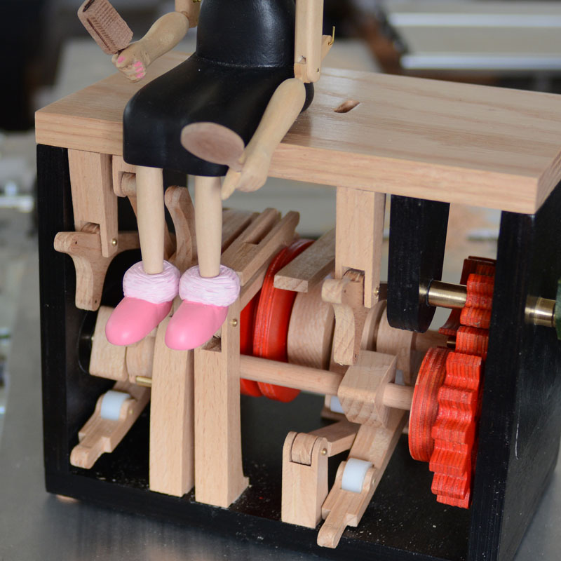
Body and feet painted with acrylics then given 3 coats of gloss acrylic lacquer followed by a matt coat to finish.
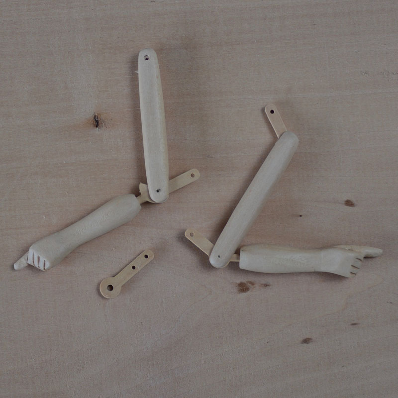
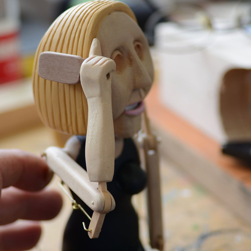
Arms carved from lime wood with linkages made from box wood. Box wood has a tight grain and is much stronger than the lime.
Inside of arm showing the top linkage made from box wood joined onto the top of the arm.
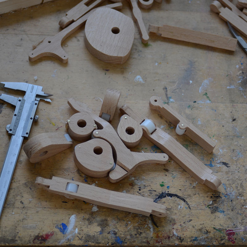
The moving parts in position. The required movement of the linkages can now be measured to calculate the size of the cams and cam levers. The brushing movement requires a slightly complicated set up. A 2 part wire connects the body to the lower arm enabling the arm to move parallel to the hair at the top of the stroke. The brass pins holding the arms in place are turned on the lathe. There is a teflon washer on each to ensure frictionless movement.
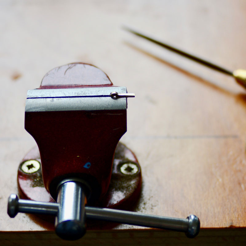
Making the anchor point for the connector mention previously. Cut from sheet brass and filed to shape with a needle file.
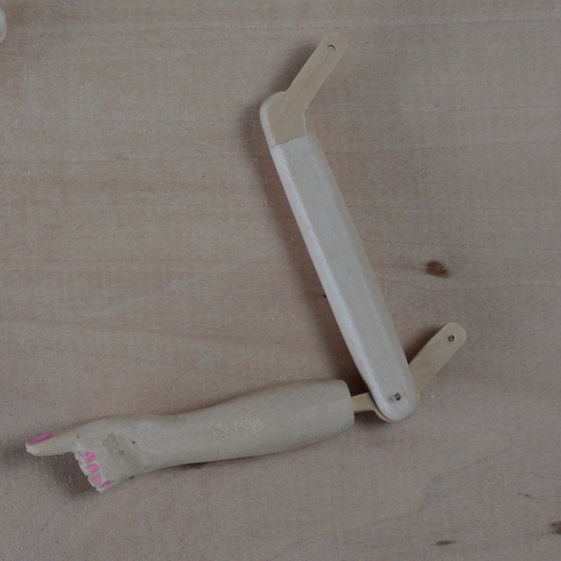
Showing the linkage in the extended position.
Showing the linkage in the bent position.
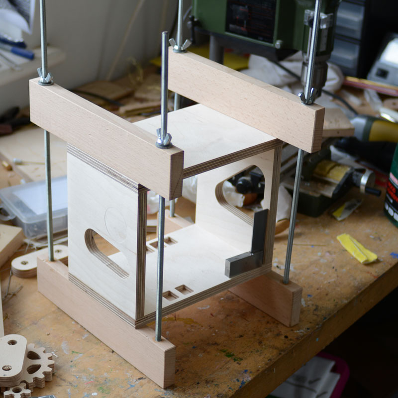
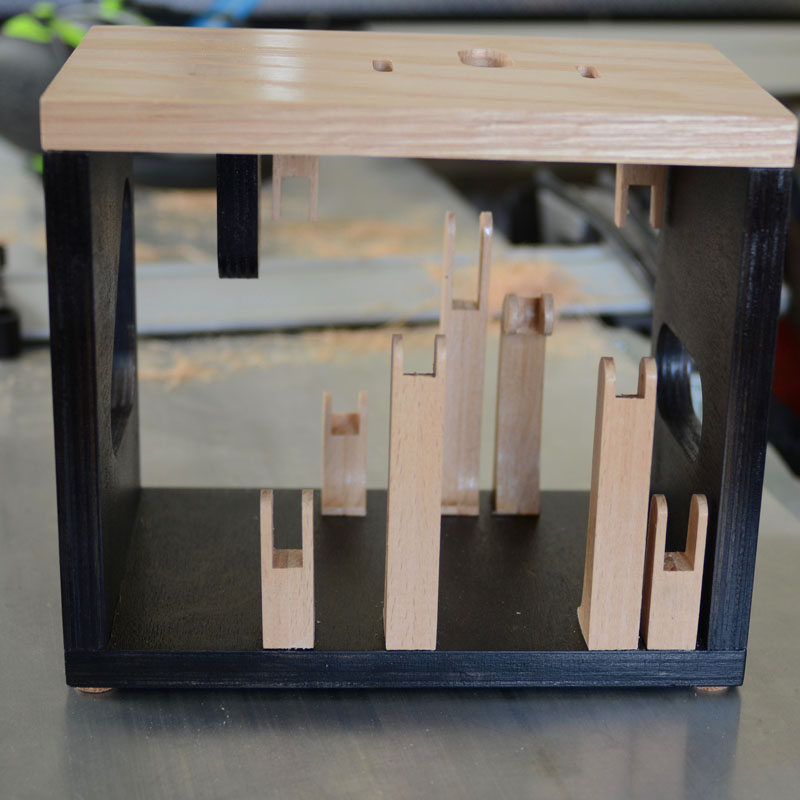
A frame being glued together using home made clamps. Only the bottom is being glued. The top will be made from oak wood and fitted towards the end of the construction.
As I am redesigning the mechanism I am using a test frame to measure the amount that the cams need to move the linkages. Here the gears and Geneva wheel are in place and work very smoothly.
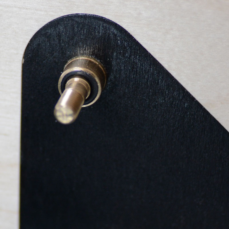
The axles are turned from brass. Here the end for the crank has a thread cut into the end to take the crank handle. All axles have nylon bushes for low friction running.
The axle bushes are set into inserts that can be removed during construction when necessary.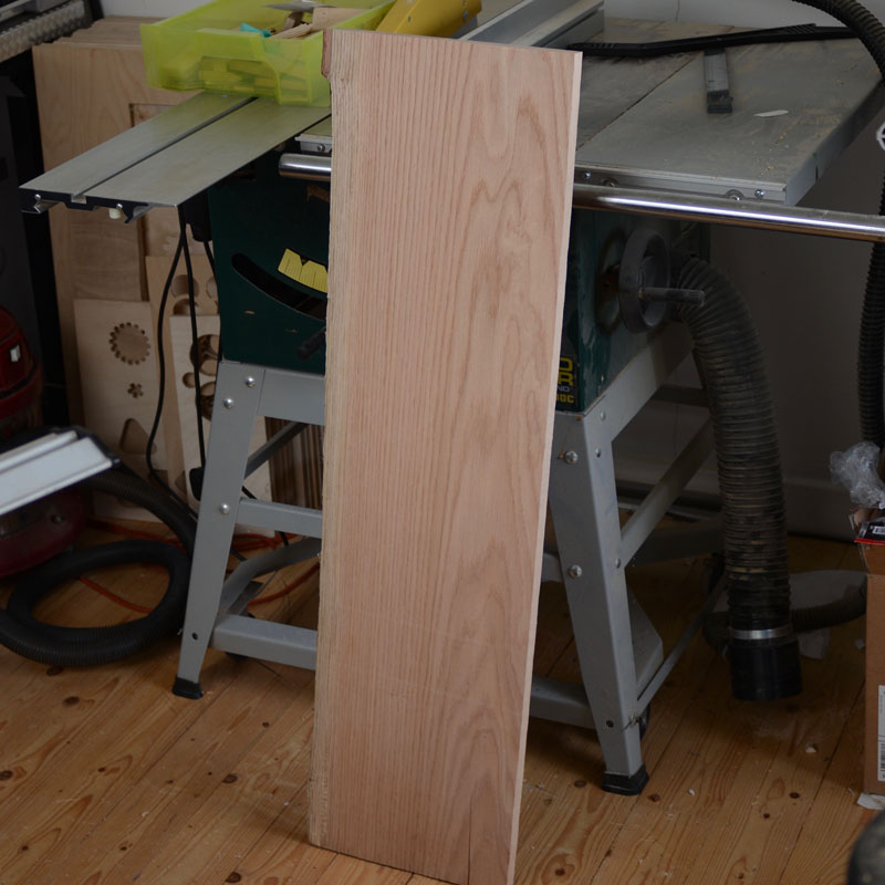
A nice plank of oak that I bought while I was visiting Wales. It was described as "pink oak" and it has a pleasing pink tinge to it. It has been air dried and I have kept it in a warm dry environment for the last 3 weeks to make sure that it is stable and doesn't warp. It seems to have been expertly dried as it has not bent in storage at all. It needs re-sawing and planing to the correct thickness before it is ready to use.
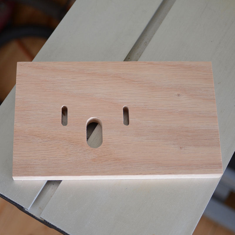
A top board made from the Welsh oak plank. The slight pink tinge suits this automaton very well.
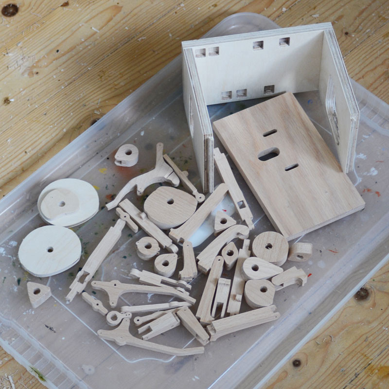
Various parts of the mechanism ready for the first coat of acrylic varnish. Most of the parts of the mechanism are made from beech wood as it is tightly grained very strong. The frame bottom and sides are made from top quality birch ply as it is very stable, keeping its size. Planks of plain wood will shrink and expand with changing humidity. The frame and other ply parts will be coloured before being varnished.
Cams and cam followers with nylon rollers for smooth running. Cams have 2 coats of wax acrylic varnish.
Test fitting of supports for cam followers
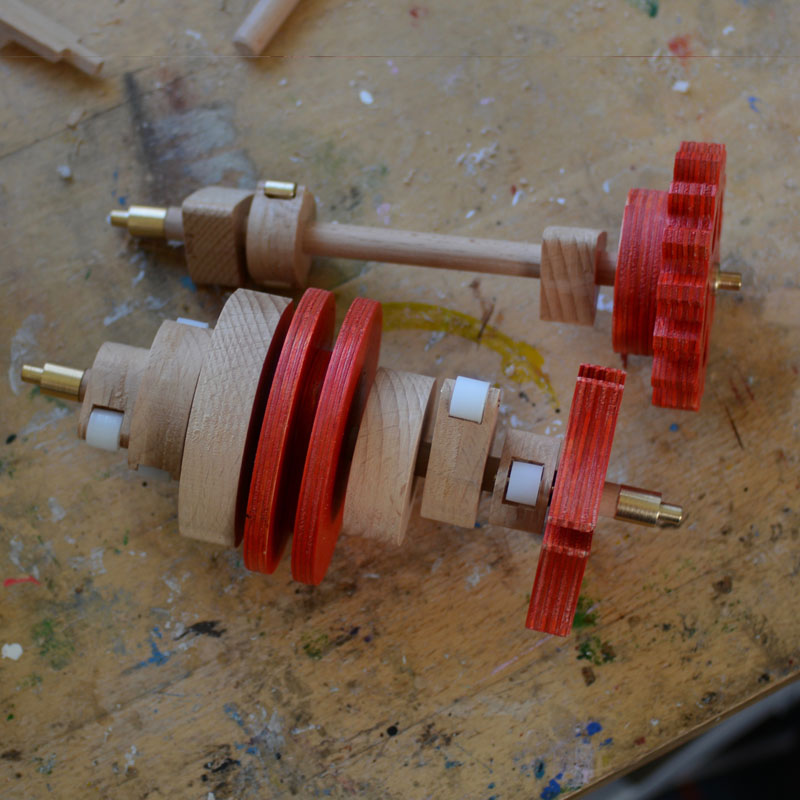
Test fitting of cams on the axles. Brass ends to the axles run in nylon bushes in the frame.
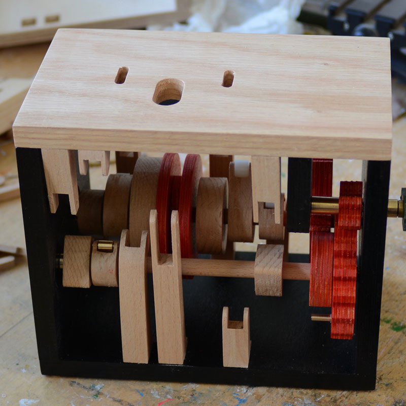
Part assembly to check cams turn unimpeded. It is very easy to design cams too large and they collide with the other axles or the support columns.
Drilling narrow holes in long beech dowels is problematic because small diameter drills tend to be too short. Here a wider hole is being drilled in the dowel that will then be capped with nylon plugs with the correct size holes.
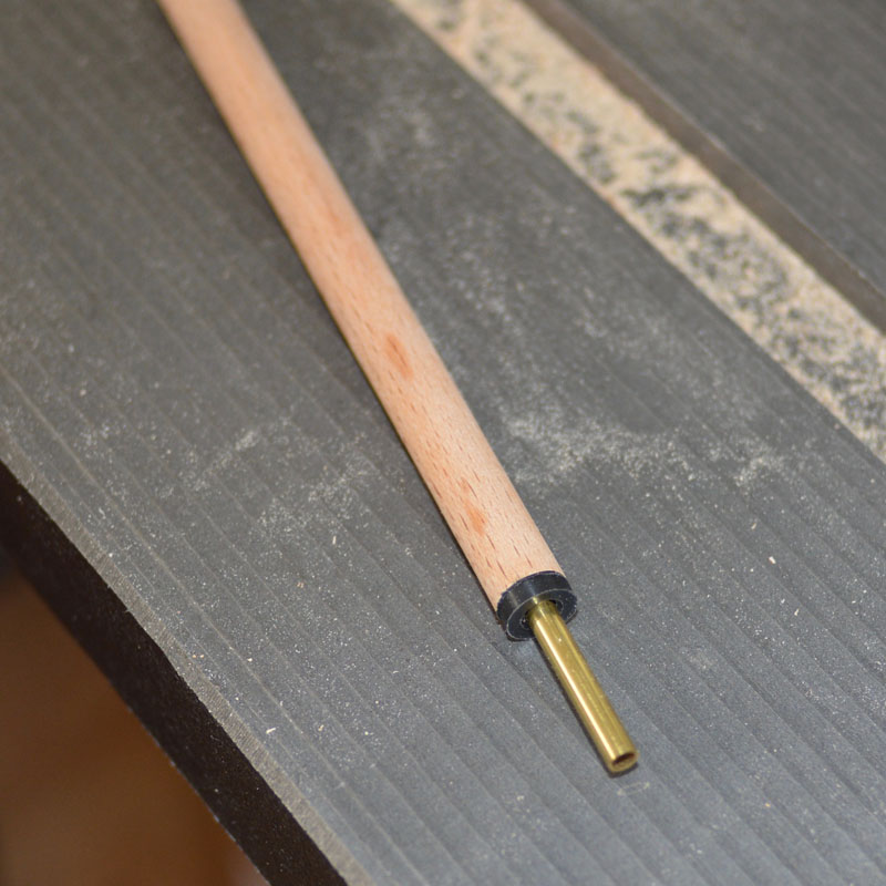
Nylon caps on the wooden dowel. These reduce friction as the brass rod only touches the cap at each end and does not rub along the length of the dowel. This brass tube controls the jaw. The eye control will run inside the tube.
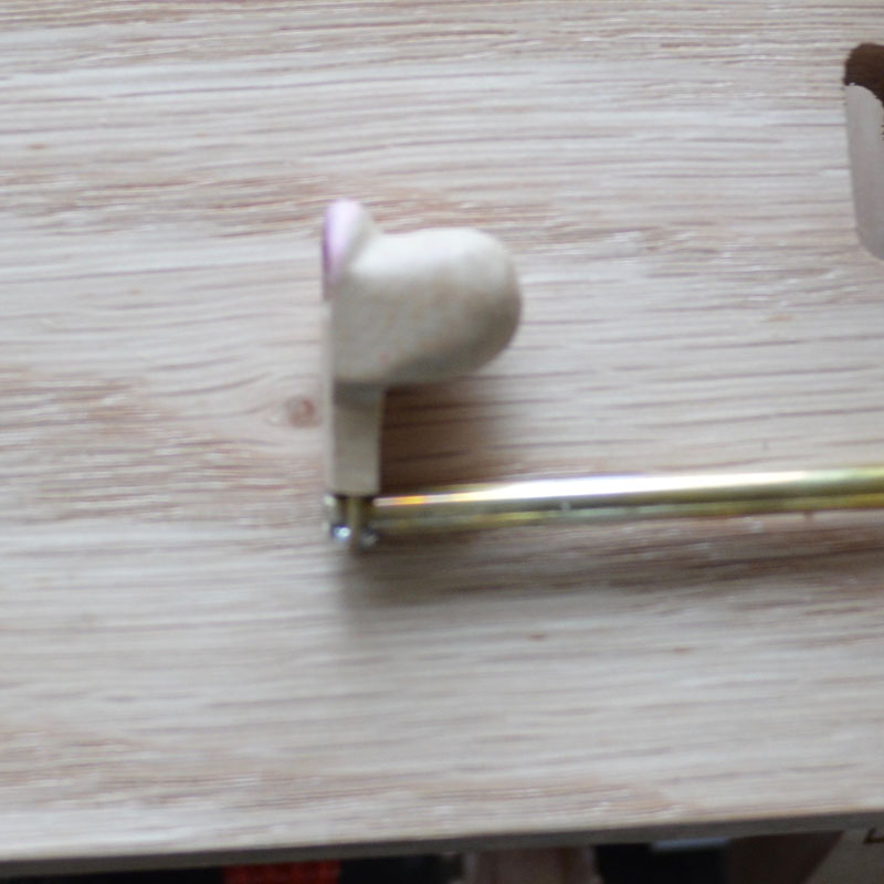
Jaw mounted on brass tube.
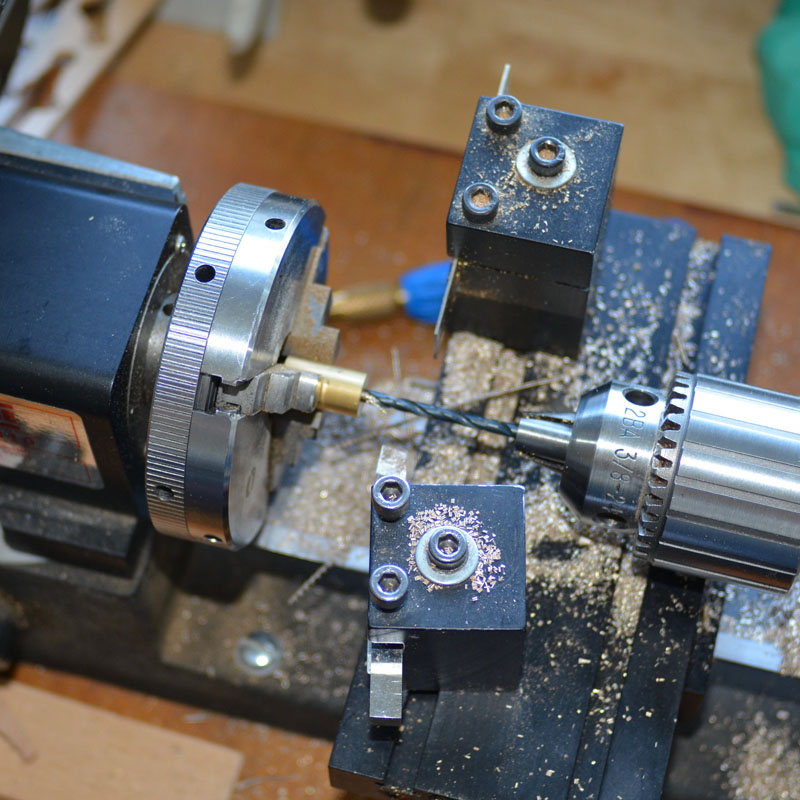
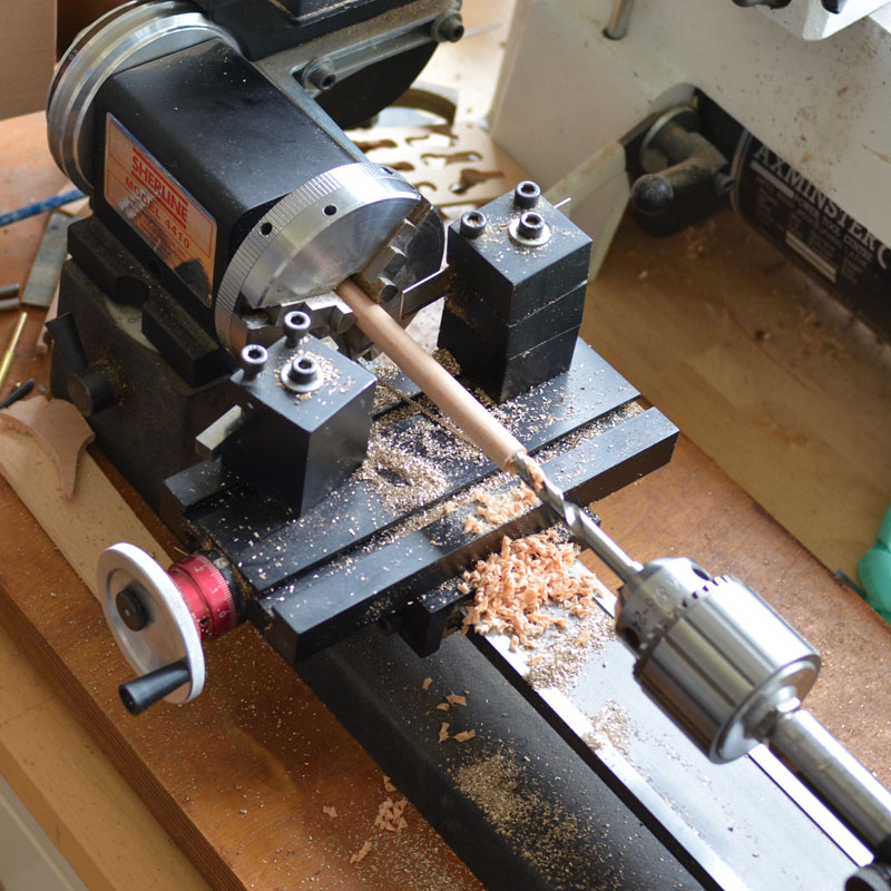
Drilling brass parts on the Shereline lathe
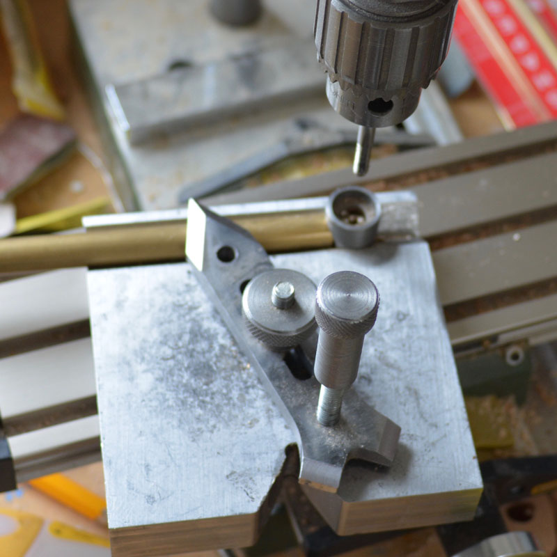
Home made clamp for holding brass rod for drilling across the diameter and tapping threads as shown here.
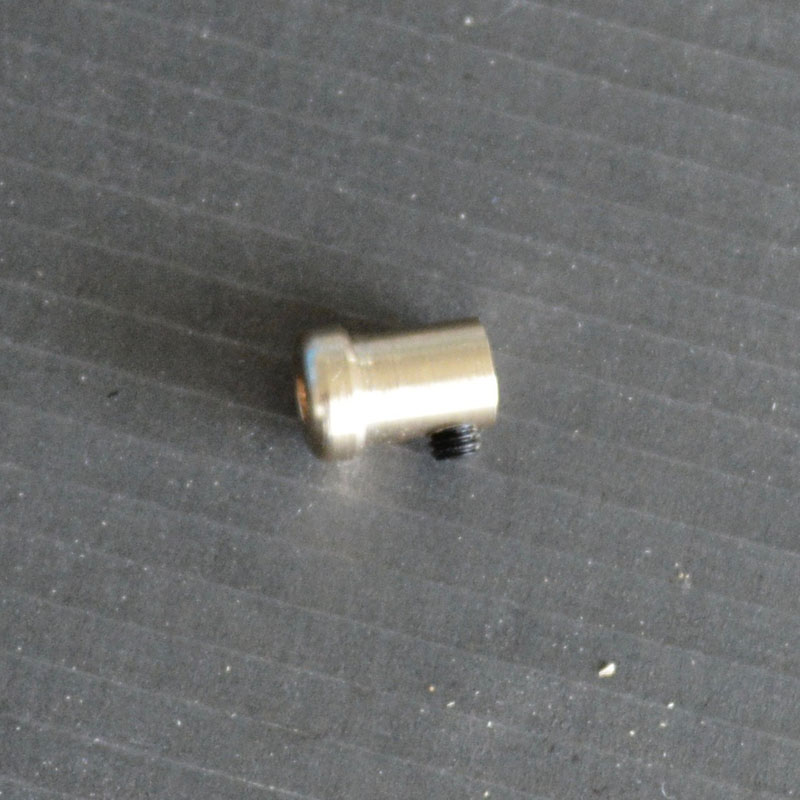
Bottom of jaw control rod with grub screw to allow fitting and adjustment.
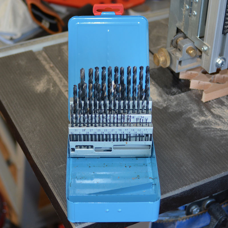
Set of British drills in 0.1mm increments. Ii took a long time to decide to buy these as they were expensive compared with many of the drill bits available. Now I don't know how I managed without them.
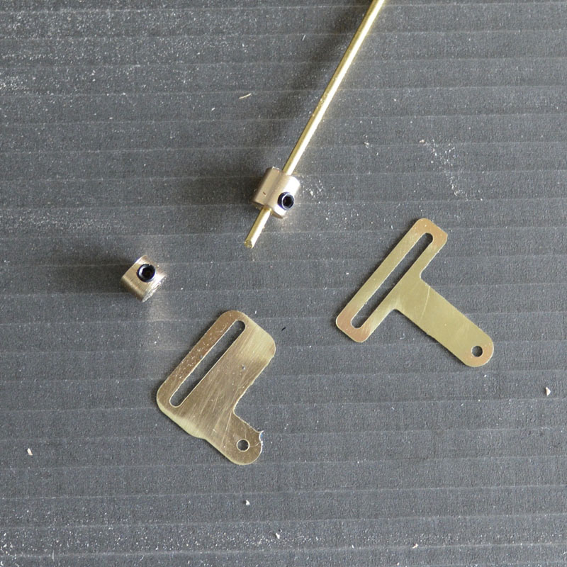
Small brass parts for the eye and breast controls.
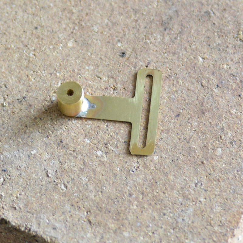
The part assembled with solder. This part will fit inside the head and control the eyes. It attaches to the control rod with a small screw to allow adjustment.
See automaton here